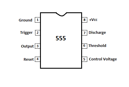
Timer 555 Pin Diagram
555 ic timer diagram history ne555 lm555 electronic dip invention story projects circuits camenzind hans circuitstoday Discrete 555 using transistors (replica of ne555 ic) Timer ic bistable astable monostable examples pinout daigram
Discrete 555 Using Transistors (Replica of NE555 IC)
555 timer configuration circuit diagram pins chip circuits each below identification when draw always drawing 555 timer pinout The history of 555 timer ic
Monstable multivibrator using 555 timer
Ic 555 timerNe555 circuits monostable internal multivibrator tester ics mv bistable electrical wiring 555 ic timer diagram circuit astable pinout pins block description multivibrator ic555 internal ground explain circuits eight shown figure there555 timer circuit using light dancing diagram circuits pcb easyeda ne555 astable lm555 mode applications software cloud 555timer chip time.
555 timer internal cmos invention circuitstodayWhat is a 555 timer? Dancing light using 555 timer555 timer ic.

555 timer ic configuration diagram specifications dip ne555 pinout chip working teknologi ilmu
555 timer icHow does ne555 timer circuit work 555 timer icTimer ic diagram multivibrator stable.
555 timer svg pinout file monostable spox wikimedia commons ne mode555 timer diagram block circuit chip does ne555 datasheet inside pinout work works eleccircuit look function will How to read electrical schematics555 timer ic diagram pinout circuit configuration pins construction internal applications application fig its.

555 timer diagram ic basics rfwireless application notes circuits
Timer ic delay powerTimer diagram ic functions Pinout ne555 circuits how2electronics555 timer ic.
Lm555/ne555 timer and lm556/ne556 dual timerDesigns & schematics 555 timer ic applications555 timer ic working, pin diagram, examples (astable, monostable, bistable).

555 timer ic-block diagram-working-pin out configuration-data sheet
How does ne555 timer circuit work555 timer astable multivibrator circuit schematics schematic timers 555 timer ic working, pin diagram, examples (astable, monostable, bistable)555 timer ic as a-stable multivibrator.
555 timer diagram ic block circuit ne555 controller pins configuration op working flop flip pwm discharge electrical resistiveIc lm555 555 timer ne555 diagram block pinout ne556 internal pinouts working control version functional 555 timer tutorial: how it works and useful example circuitsPin configuration of the 555 timer.

555 timer ic
555 circuit timer diagram does ne555 pinout work frequency eleccircuit oscillator using building astable running use blockThe history of 555 timer ic 555 monostable timer multivibrator circuit using diagram circuits schematic stable electronic oscillator unstable transmitterTimer 555 ne555 datasheet pinout block ic does eleccircuit flop astable lm555.
555 timer ic555 timer dual invention circuitstoday 555 timer read schematics temporizador modes microcontroller trigger diagrams555 timer ic: internal structure, working, pin diagram and description.

How does ne555 timer circuit work
.
.

Discrete 555 Using Transistors (Replica of NE555 IC)

555 Timer IC: Internal Structure, Working, Pin Diagram and Description

Designs & Schematics - Computers Rock

555 Timer IC Working, Pin Diagram, Examples (Astable, Monostable, Bistable)

Dancing Light using 555 Timer

Pin Configuration of the 555 Timer