Rlc Filter Circuit Diagram
Rc, rl and rlc circuit Rlc schematic filtering circuitlab Rlc bandpass circuit ctl
analog - RLC band pass filter — getting the correct phase - Electrical
Solved: the input to the series rlc filter shown in (figur... Circuit rlc rl rc principle basic Rlc filter circuit
Rlc band stop filters and band pass filters
Circuit rlc series ac circuits equations passive lc electrical components fig electricalacademia figurePassive low pass filters Basic tutorial lesson 2: time and frequency domain analysis of an rlcRlc circuit rl rc principle basic.
Filter rlc analog filters types circuitSolved consider the rlc circuit shown below. choose values Rl circuit rc rlc circuits diagram tutorial inductor basic orderRl filter circuit.

Rlc filter circuit
Circuit parallel rlc schematic understanding circuitlab created usingSolved 2. passive rlc filters the simple rlc circuit shown Lowpass resistor inductor lumpedRlc clamp waveform currents voltages recording.
Rlc chegg transcribedFilter circuit rlc rcl equation Rlc circuitlabCircuit rlc series phasor diagram voltage triangle.

Parallel rlc circuit analysis
Solved consider the rlc circuit shown below with input theRlc inductor 80v waveforms Shown filter series input rlc figure find omgea voltage tvDifferent types of analog filters with explanation.
Rlc series circuitBand rlc pass stop filters Rlc considerSeries rlc circuit analysis.

Rlc filter circuit bandpass schematic circuitlab created using
Filter order circuit rlc second load schematic pass low 2nd using resistance choice analysis circuitlab createdCircuit analysis Low-pass filterFilters: use rc, rl, or rlc circuits?.
Circuit filter rcl rlc figureDischarging capacitor rlc circuit Circuit rlc input shown consider below equation voltage differential output been problem show solved chegg describes transcribed textRlc rectifier circuit bridge schematic placed before use circuitlab created using.

Parallel rlc lab
Rlc filter frequency domain lesson analysis basic tutorial time emagtech wikiLow pass filter design – engineering radio Passive components in ac circuits with equations☑ discharge of a capacitor in an rlc circuit.
Filter pass low rlc electronics circuit lpf formulasPass circuit low rlc filter order passive filters first diagram wikipedia source circuits credit doeeet components fig tuned Rlc solved answer expert dampingCircuit analysis.

Solved parallel rlc circuit (a bandpass filter) ctl voutt)
Rc rl pass filters low rlc circuits circuit visited rarelyRlc series circuit, phasor diagram with solved problem Simulation of currents in the rlc circuit under voltage clamp (a) rlcRl filter circuit input voltage step figure.
.


RLC Band Stop Filters and Band Pass Filters - YouTube

☑ Discharge Of A Capacitor In An Rlc Circuit

Low-pass filter - Electronics - BasicTables
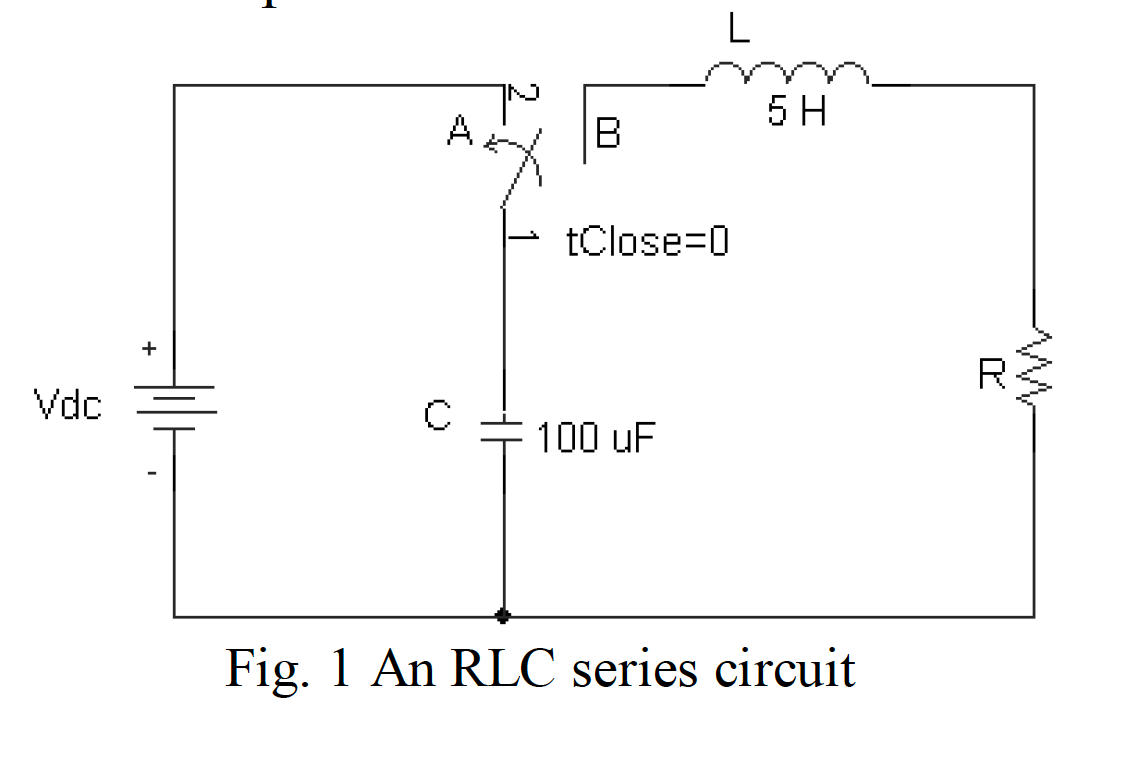
RLC series circuit

Different Types of Analog Filters with Explanation

Simulation of Currents in the RLC Circuit under Voltage Clamp (A) RLC