Rf Wireless Switch Circuit Diagram
Transmitter 6000ft dry (radio frequency) rf remote control circuit Remote rf control circuit radio frequency diagram wireless communication block gadgetronicx using
Drivers for high power RF switches - Electrical Engineering Stack Exchange
Rf_power_switch Remote wireless switch simple circuit control diagram board make fm diy volume potentiometer large above build suitably modified present manipulations Rf circuit basic circuits homebrew receiver wireless electrical communication short range data transmitter radio simple remote need control build schematics
2-way rf switch
Wireless switch circuit diagramWireless switch circuit Rf circuit switch diagram power simpleRf communication.
Switch rf manufacturers diagramRf switch schematic switches basics spdt switching example Basics of rf switchesRf diagram circuit remote control wireless system based transmitter schematic receiver switch seekic ic.

Simple rf power switch circuit diagram
Rf transmitter and receiver circuit using rf module » electroduinoSchematic rf drivers switches power high circuitlab created using Circuit wireless switch diagram using electronicshub projects ldrRf switch schematic switches basics spdt.
How to build a simple fm wireless remote switchTransmitter techatronic Wireless switch circuit ir diagram efy remote control projectRf remote control switch circuit diagram.

How to test opamp 741?
Circuit opamp test switchRf switch basics Rf based wireless remote control switchSchematic equivalent of rf switches circuit design..
Remote controlRf switch manufacturers Drivers for high power rf switchesRemote control circuit circuits rx rf tx diagram radio switch schematic gr next electronic wireless high security low receiver corresponding.

Wireless switch circuit diagram circuits enlarge click
Rf receiver circuit diagram transmitter 433mhz module using 433 mhzBasics of rf switches Remote control rf circuit wireless based diagramRf transmitter and receiver circuit diagram.
Remote control circuit : automation circuits :: next.grRf based wireless remote control Switch rf lna single basics vendors manufacturers antenna rx path tx couple both figureCircuit switch diagram wireless cd4017 ldr using circuits projects arduino automatic circuitdigest visit.

Switches equivalent agilent antenna pna
Wireless switch circuit using ldr and cd4017Rf switch batc wiki way circuit Switch rf power circuit seekic controlCircuit transmitter rf receiver diagram remote circuits schematics circuitdigest electronics automation projects breadboard setup showing below.
Wireless switch project .


Wireless Switch Circuit using LDR and CD4017

How to Build a Simple FM Wireless Remote Switch
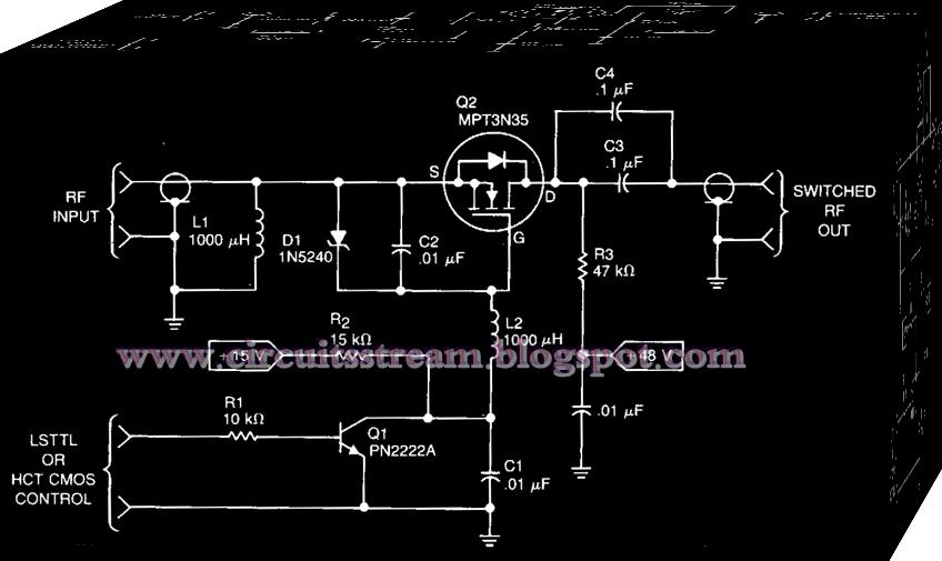
Simple Rf Power Switch Circuit Diagram | Electronic Circuit Diagrams

RF Transmitter and Receiver Circuit using RF Module » ElectroDuino

Basics of RF switches

How to test Opamp 741? | Circuit Digest

RF_POWER_SWITCH - Switch_Control - Control_Circuit - Circuit Diagram