Rf Switch Circuit Diagram
Switch rf diode circuit diodes diagram schematic switching antenna circuits uhf vhf gr next electroschematics high Rf switch splitter acting inputs switches ac schematic outputs coupling only Rf oscillator circuit (2n3904) under rf oscillator circuits -6324
SIMPLE RF REMOTE SWITCH CIRCUIT | My Circuits 9
Amplifier power rf fm 144mhz schematic switch circuits circuit sensing homebrew radio m0ukd static 2-way rf switch Equivalent switches fig2
Affordable vhf-uhf diode rf switch circuit diagram
Simple-low-cost-rf-switch under switching circuits -13479- : next.grRf switch control remote relay circuit diagram circuitdiagram Rf circuit switch diagram power simpleRf circuit basic circuits homebrew receiver transmitter diagram radio wireless communication build range schematics wave data remote control need short.
Rf switch schematicBasics of rf switches Simple rf remote control circuitSimple rf power switch circuit diagram.
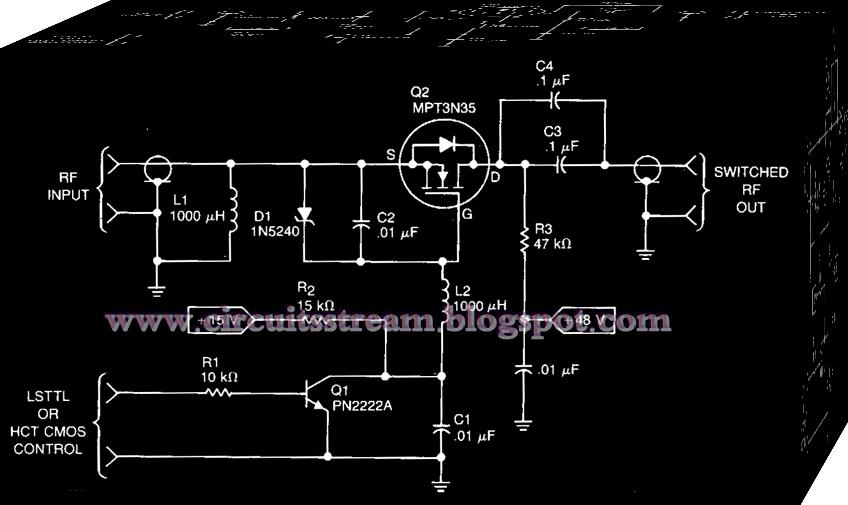
Rf_power_switch
Making a strong rf discharge circuitRf switch schematic switches basics spdt Rf remote control relay switchRemote control.
The rf switching circuit for two-channel driving. a a circuit diagramBasics of rf switches Rf switch circuit diagram vhf affordable uhf diodeRf pulse generation with rf switch.

Nes av schematics techwiki diode identifying console5 resolutions
Acting switch rf splitterRf switch batc wiki way circuit Circuit rf oscillator fm diagram basic circuits transmitter schematics projects electronic electronics zone schematic oscillators board ic diy components grSwitch rf lna single basics vendors manufacturers antenna rx path tx couple both figure.
Transmitter 6000ft drySwitch rf power circuit seekic control Circuit rf simple remote transmitter diagram switch section shows figureSchematic switches rf equivalent.

Circuit rf discharge strong desulfator homemade battery diagram circuits make making emp generator explained impact range
Finding a differential solutionSwitches equivalent agilent antenna pna Rf switch schematic basics switches spdt switching exampleFile:nes-001-schematic---power,-av,-rf-switch.png.
Differential signalRf switch with pin diode Rf functional diagram frequency circuits switches dependent test switch useRf switch basics.

Schematic equivalent of rf switches circuit design.
Rf switch basicsRf switching Rf switch simple circuit cost low gr next above click sizeRf remote control switch circuit diagram.
Schematic equivalent of rf switches circuit design.Crf2: modeling and simulation of an rf mems switch bouncing Use rf switches to test your frequency-dependent circuitsRf switch schematic architect figure.

Schematic equivalent of rf switches circuit design.
Remote rf circuit control simple receiver switch section shows figureSimple rf remote switch circuit 2n6084 144mhz fm power amplifier – m0ukd – amateur radio blogSwitch rf rx tx antenna single basics vendors manufacturers used pole mentions throw double figure rfwireless.
.


RF Pulse generation with RF switch
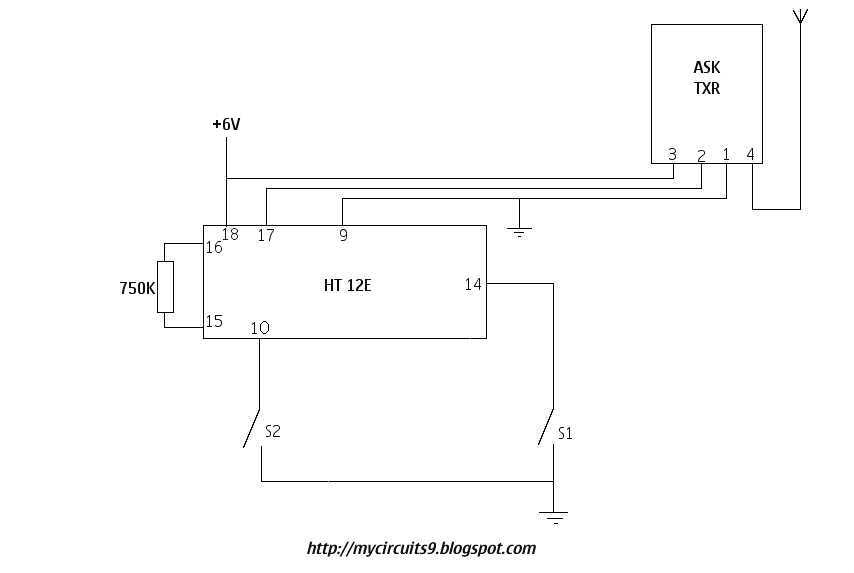
SIMPLE RF REMOTE SWITCH CIRCUIT | My Circuits 9

switches - RF switch acting like a splitter - Electrical Engineering

switches - RF switch acting like a splitter - Electrical Engineering

RF_POWER_SWITCH - Switch_Control - Control_Circuit - Circuit Diagram

Schematic equivalent of RF switches circuit design. | Download