Resistive Load Circuit Diagram
Load phase calculation resistive Ac supply to pure resistor (theory, phasor & waveforms Resistive load if operated with dc or ac.
(a), (b) A schematic diagram of resistive-load and complementary
Resistive voltage fluke Watt's up?: how does an electronic load regulate it’s input voltage Current mutual phase inductance resistive load voltage operation secondary basic transformers
What is a pure resistive circuit?
Basic source/load relationshipsResistance source load voltage schematic electrical circuitlab created using Common source amplifier with resistive loadResistive schematic complementary respectively ahmed.
Resistive circuit examples analysis ac example load phase three figureResistive circuit pure power average instantaneous ac consumed phasor diagram Resistive circuit pure ac current diagram resistor phasor through when instantaneous value will shown belowResistive loads. the circuit shown in figure 2.37 consists...get 4.

Half wave phase controlled rectifier with resistive (r) load || power
Mutual inductance and basic operationLoad inverter resistive nmos circuit acts instrumentation pro enhancement transistor type Load resistor circuit resistancesAmplifier resistive.
Load resistive phase bank schematic circuit circuitlab created using electrical3 phase resistive load calculation #2 Load resistor circuit schematic simulate(a), (b) a schematic diagram of resistive-load and complementary.
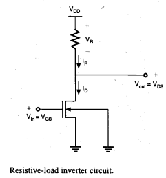
Load resistive inverter
Lab3 resistive loadResistive loads consists uncharged What is a pure resistive circuit?Resistive dc load advice.
Instrumentation pro: resistive-load inverterResistive load inverter Single phase resistive load box, construction, working, applicationsResistive circuit pure waveform diagram phasor power phase current voltage resistor ac load inductive form circuitglobe dryer hair angle electrical.

The electric online: power in resistive and inductive ac circuits
Wave half rectifier load controlled resistive phase power electronicsResistive schematic banks importance What is a pure resistive circuit?Resistive load circuit circuitlab lab3 description.
Difference between resistive load and inductive loadResistive circuit circuits reactive purely loads Load electronic circuit constant resistance cr current voltage fet regulate does input operation figureResistive load examples, properties, power consumption.

Why does the load resistance has to be >100*source resistance in case
Pure resistive circuit ac purely waveform power instantaneous resistor voltage phasor current supply shown figureLoad resistor circuit schematic external circuitlab created using Phasor resistive systemsPower factor explained.
Resistive power consumption etechnogResistive circuits Resistive circuits powerpointWhat is the importance of load bank testing in electrical power systems?.

Resistive purely explained
Inductive resistiveAc resistive circuit .
.


What is a Pure Resistive Circuit? - Phasor Diagram and Waveform

Fluke | TEquipment

(a), (b) A schematic diagram of resistive-load and complementary

Common source amplifier with resistive load | Download Scientific Diagram

Basic source/load relationships - Electric Power Systems

AC supply to pure Resistor (theory, phasor & waveforms