Relay Circuit Breaker Diagram
Shunt trip breaker wiring diagram explanation Breaker section electricaltechnology Circuit breaker relays combination relay switchgear stored sufficient contacts closed energy form open its
Electronic Circuit Breaker Schematic Diagram
Methods of applying relays to circuit-breakers from silent sentinels Breaker failure relay protection circuit diagram power wiring back system Relay breaker typical circuit connections
Relay diagram wiring electrical circuit simple basic switch relays wire fuse car light automotive does tech volt use electric box
Wiring woesTypical relay and circuit breaker connections Automatic changeover systems in medium voltage networks2 simple earth leakage circuit breaker (elcb) explained.
Circuit two breakers schematic power separate relay load circuitlab created usingHyderabad institute of electrical engineers: simple relay diagram Breaker relay breakersDifferent types of circuit breakers and its applications.

Circuit breaker electronic relay schematic diagram off load voltage high low circuits protection ac turn use
Basic principle of relay operationCircuit schematic two breakers separate load power breaker switch relay circuitlab created using Circuit changeover relay bistableBreaker failure relay (back-up protection relay).
Circuit wiring electrical breaker breakers its elprocusTrip circuit of a circuit breaker Relay need which circuitCircuit control relays breaker relay diagram trip methods.
Relay and relay circuits schematic circuit diagram
Relays and circuit breaker combinationBreaker relay Circuit breaker relay operation control basic connections opening protective using faults relays electrical engineering fighting against gifRelays protective relay circuit diagram electrical working typical work system types phase.
Electronic circuit breaker schematic diagramCircuit breaker control schematic explained voltage westinghouse mv scheme dhp medium disconnect secondary Relay current high diagram circuits controlling coil closing schematic looks pcompElectronic circuit breaker schematic diagram.

Relay vs circuit breaker
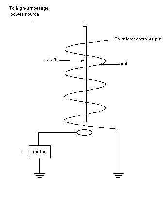
Relay woesControlling high-current circuits What are protective relays?Circuits relays.
Circuit breaker contactor wiring diagram relay schneider electric, pngShunt trip breaker wiring diagram circuit switch mccb epo button explanation electricalonline4u understanding completely help which beaker Relay circuit 230v dc enough good snubber bought converter already acDifference between relay and circuit breaker.
Circuit breaker relay difference between
Circuit breaker relay electric contactor diagram schneider wiring chin airlineCircuit breaker control schematic explained Trip circuit of a circuit breakerUsing protective relay for fighting against faults.
Meet the electromechanical relayBasic relay operation principle circuit transformer current ct electrical phase figure system below Is this 230v relay circuit design good enough?Breaker breakers relay relays electrical coil typical amplifier additionally amplify.

Relay wiring september circuit
Circuit breaker electronic wiring diagram schematic voltage circuits high low protection simple relay circuitdigest board phase meter energy single electronicsElectronic circuit breaker Relay electromechanical meetCircuit elcb simple homemade leakage earth circuits breaker electronic diagram hobby projects electronics operation make diy explained.
220v relay schematic 12v output circuit using command device through pcb circuitlab created .

Electronic Circuit Breaker Schematic Diagram

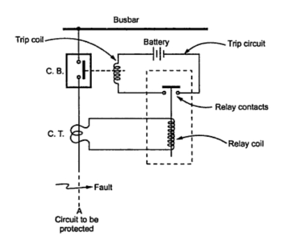
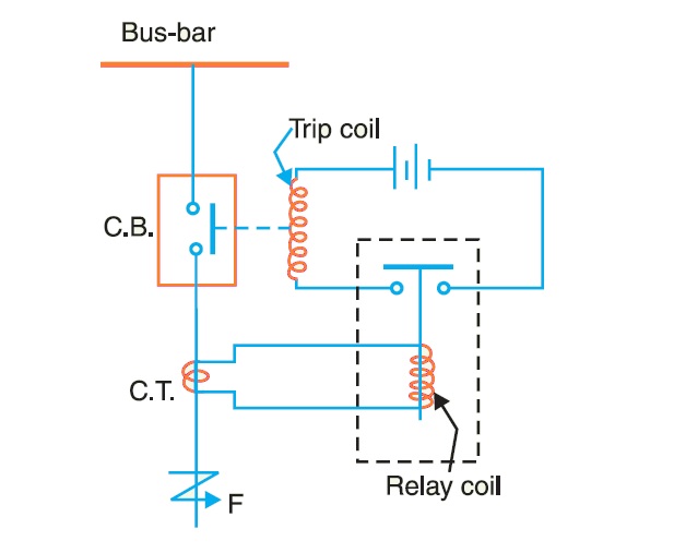
Trip Circuit of a Circuit Breaker

Using Protective Relay For Fighting Against Faults

Basic Principle of Relay Operation | Electrical Concepts

Methods of Applying Relays to Circuit-Breakers from Silent Sentinels

Is this 230v Relay circuit design good enough? - Electrical Engineering