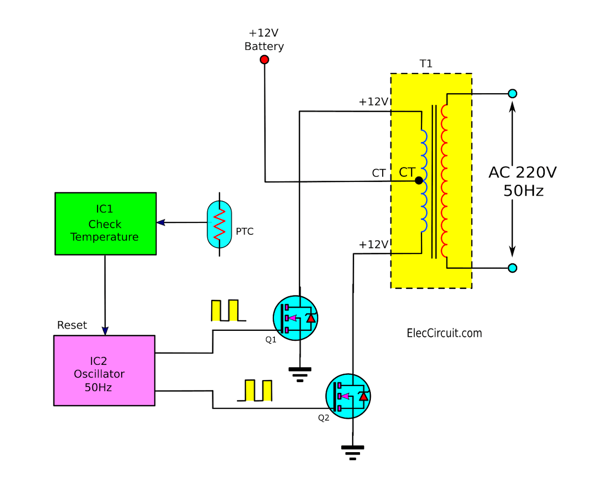
Push Pull Inverter Circuit
Push-pull output stage Push-pull-inverter analog-cmos-design || electronics tutorial Basic_push_pull_converter_circuit
Typical diagram of the push-pull forward inverter | Download Scientific
(pdf) current-fed parallel resonant push-pull inverter with coil flux Mosfets in push-pull configuration: possible short circuit during Inverter circuit page 3 : power supply circuits :: next.gr
Inverter push pull dc ac power circuit gr next inverters supply circuits
Push pull circuit converter seekic basic supply powerSmps diagram converters symmetrical transformer talema isolation galvanic Dc dc converter3: single phase push pull inverter.
Push-pull inverter with mosfets connected directly in parallelDc to dc converter using push pull topology with sg3525 Inverter circuitPull inverter mosfet 220v threshold voltage parallel mismatch driving.

20 watt push-pull cfl inverter circuit – circuits diy
Mosfet mosfets circuitlab pushpullModified sine wave inverter using pic microcontroller Push-pull inverter circuit which is controlled by sinusoidal pwmPush-pull inverter circuit which is controlled by sinusoidal pwm.
Push pull inverter cmos configuration analog electronics tutorial equivalent signal circuit shown smallSmps: symmetrical isolated converters : the talema group Push pull inverterCircuit pull diagram transformer inverter push wave sine microcontroller modified using pic voltage ac step microcontrollerslab pusl.

Inverter pull royer oscillator smps inverters fed
Push-pull-inverter analog-cmos-design || electronics tutorialInverter phase Inverter push mosfetsOperation of 200 watt inverter diagram – electronic projects circuits.
Push pull inverterTypical diagram of the push-pull forward inverter 12v inverter circuitPush-pull dc-ac inverters.

Tuning push-pull inverter for best efficiency
Push-pull inverter circuit.Push pull output pushpull stage circuit cir spice file Push pull fed current circuit induction resonant inverter parallel coil flux heating applications controlPush pull inverter efficiency tuning.
Typical diagram of the push-pull forward inverterPush-pull inverter circuit. Inverter pull pwm controlled sinusoidalInverter push pull cmos signal small circuit mosfet analog electronics tutorial applying kcl.

Inverter circuit pwm controlled sinusoidal uninterrupted factor correction implementation microcontroller
Push pull inverterDiagram block inverter watt inverters 200watt circuit operation mosfet 50hz circuits electronic output oscillator eleccircuit diagramm high projects figure Push-pull inverterCircuit push pull diagram sg3525 schematic induction using core pwm pulse inverter controller dc converter power heating mosfet saturation regulator.
Inverter cfl pullInverter overall .


Tuning Push-Pull inverter for Best Efficiency
Typical diagram of the push-pull forward inverter | Download Scientific

Push-Pull DC-AC Inverters

Push-Pull Inverter Circuit. | Download Scientific Diagram

dc dc converter - Push pull core saturation - Electrical Engineering

Push-Pull Output Stage

Push-Pull-Inverter Analog-CMOS-Design || Electronics Tutorial