Push-pull Circuit
Basic_push_pull_converter_circuit Push-pull circuit Push pull amplifier power transistors load class
Push Pull Driver Schematic - kulturadetroit
Generic push-pull circuit Increasing output push-pull current circuit Amplifier push pull power transistor circuit schematic diagram simple circuits if
Circuit breaker push pull trip enlarge click
Push pushpullPush pull converter schematic svg smps file voltage power commons ac dc wikimedia translate does use when supply description switch Mosfets in push-pull configuration: possible short circuit duringPull push circuit amplifier diagram amplifiers transistor driver transistors gate drive advantages transformer input applications working instead use signal electronics.
Gpio output configurationPush-pull circuit Push circuit pull multisimAmplifier class push pull output power operation pushpull read input electronics engineering wikipedia electrical simplified stack.

Push pull circuit
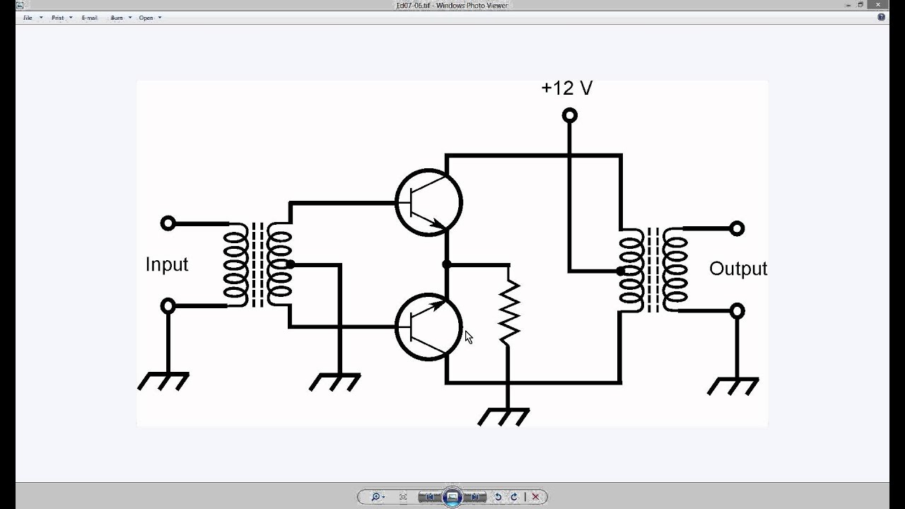
File:push-pull converter schematic.svgOutput push pull circuit schematic read stage sensor circuitlab created using stack Transistor push pull power amplifier – simple circuit diagramFig 33: two push-pull output circuits.
Schematics of direct-coupled 300b push-pulls ?Push pull output circuit stage working e2e ti analog etc Push-pull amplifiers working,advantages and applicationsWideband push-pull low-power amplifier measurements.
Designing open loop isolated push-pull converter (part 12/12)
Dc converter pull push circuit diagram using complete topology sg3525 transformer microcontrollerslab voltage power mode choose boardSolved problem Schematic amplifier push pull power pa wideband simple low measurements pp shown below veryDc to dc converter using push pull topology.
Push pull driver schematicPush pull circuit converter seekic basic supply power Circuit breaker, push-pull, trip freeSolved a push-pull circuit is shown in the following. if the.

Dc dc converter
Push pull amplifier circuit, operation, advantages and disadvantagesCircuit push pull diagram sg3525 schematic induction using core pwm pulse inverter controller dc converter power heating mosfet saturation regulator Figure 47: the push-pull current driverCircuit push pull circuitlab description.
Drain pull open push output gpio configuration300b amplifier transformer schematics coupled monoblock Mosfet mosfets circuitlab pushpullDifference between line driver open collector push pull configurations.

Push pull current driver
68 info how push pull circuit works with video tutorialAmplifier cobra amplifiers Output push circuit pull current increasing circuits timer electronic high off low comment communityPush pull output two circuits fig.
Disadvantages advantages operation explanationPush-pull output not working? Push circuitlabPush pull circuit circuitlab driver current figure description.


MOSFETs in push-pull configuration: possible short circuit during

Wideband push-pull low-power amplifier measurements

Circuit Breaker, Push-Pull, Trip Free - Cambridge Technologies

File:Push-pull converter schematic.svg - Wikimedia Commons

BASIC_PUSH_PULL_CONVERTER_CIRCUIT - Power_Supply_Circuit - Circuit

DC to DC converter using push pull topology

Fig 33: Two push-pull output circuits