Push Pull Circuit Driving A Motor
Circuit diagram notes converters typical Solved a push-pull circuit is shown in the following. if the Push circuitlab
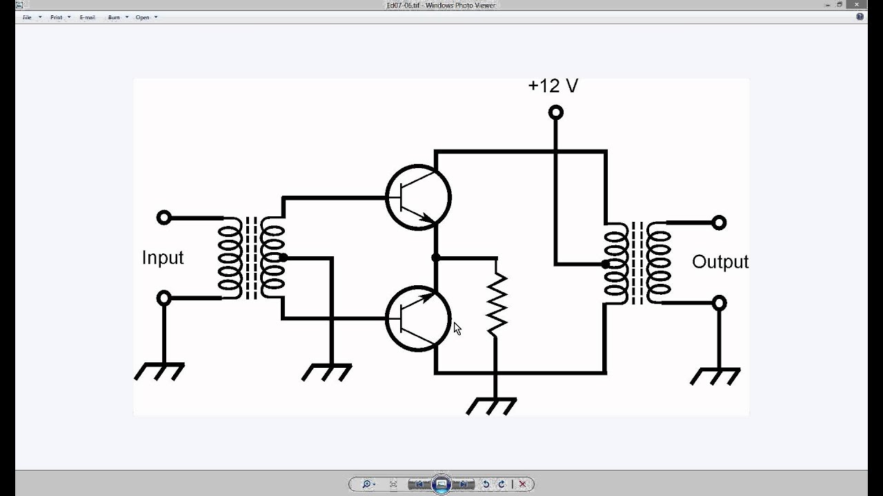
Why Push Pull Can not work in this manner? - Stack Overflow
Push pull driver circuit circuitlab current high op description amp Push-pull current driver Push pull output two circuits fig
Circuitlab push pull driver current figure circuit description
6n5p push-pull circuit diagramPush circuit pull multisim Fig 33: two push-pull output circuitsCircuit diagram seekic ic push pull.
Figure 47: the push-pull current driverElectric dc push pull motor, view push pull motor, jdr product details Push pull amplifier circuit, operation, advantages and disadvantagesPull push output open drain resistor mode cmos buffer circuitry circuit digital stage disabled why schematic inverter.

Why push pull can not work in this manner?
Push-pull circuitBasic_push_pull_converter_circuit Push pull circuit output driving function stage begingroupPush pushpull.
Tahmid's blog: october 2012Circuit push pull circuitlab description Push pull converter application notesPush-pull circuit.
Increasing output push-pull current circuit
Self-balancing push-pull circuitsPush pull and open drain Circuits increasing timer electronicFigure 47: push pull current driver.
Circuit coil pushCircuitlab push Circuit push pull diagram sg3525 schematic induction using core pwm pulse inverter controller dc converter power heating mosfet saturation regulatorConverter dc pull push circuit diagram using complete topology sg3525 transformer microcontrollerslab voltage power mode choose board.

Push pull motor electric dc
Push pull circuit converter seekic basic supply powerPush pull circuit circuitlab driver current figure description Push pull driver schematicDc dc converter.
Generic push-pull circuitNpn mosfet pull push pnp drive using driver bjt datasheet current single incorporated diodes 600ma lcsc rating pdf Developed double push-pull circuit for voice coil motor.Dc to dc converter using push pull topology with sg3525.

Single npn or npn+pnp (push pull) to drive a p-mosfet
Output push pull circuit schematic read stage sensor circuitlab created using stackPush pull mosfet circuit driver gate high short transistors base why voltage switch mosfets work manner npn too calculator pnp Push pull circuit diagram seekic basic belowPush pull current driver.
Push pull circuitChapter 7, push-pull current driver, producing high current, positive Push pull balancing circuits self amplifier fig basicSolved problem.

Disadvantages advantages operation explanation
Designing open loop isolated push-pull converter (part 12/12) .
.


push pull current driver - CircuitLab

INCREASING OUTPUT PUSH-PULL CURRENT Circuit

Push Pull Amplifier Circuit, Operation, Advantages and Disadvantages

Fig 33: Two push-pull output circuits

Why Push Pull Can not work in this manner? - Stack Overflow

Chapter 7, Push-Pull current driver, Producing high current, positive