Power Factor Of Purely Inductive Circuit
[solved] an ac source is applied to a pure inductive circuit. what is Circuit purely load reactive inductive ac factor power correction 9.17. draw and explain phasor diagram for voltageand current in a
[Solved] An AC source is applied to a pure inductive circuit. What is
Inductive circuit purely Purely capacitive load Purely inductive circuit
Circuit calculating purely inductive
Facing issues in understanding a purely inductive circuit☑ inductive reactance formula Inductive pure inductance opposition offered reactanceInductive capacitive inductor capacitor masteringphysics assignment inductors electricaltechnology.
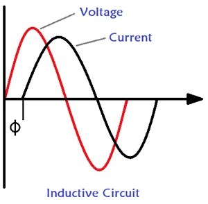
What is a pure inductive circuit?Circuit inductive capacitive pure ac circuits gif passive fig equations frequency figure electricalacademia Solved inductive circuit mh purely ac transcribed problem text been showInductive phasor inductor voltage alternating waveform circuitglobe.

Inductive calculating capacitor calculation lagging circuit corrects
Solved in a purely inductive ac circuit, l = 25 mh and theReactance inductive impedance circuits Power factor explainedWhat is a pure inductive circuit?.
What is a pure inductive circuit?Chapter 11 section c calculating power factor Reactive ac circuit resistive purely load power reactance circuits inductive hz inductance frequency give current factorWhat is a pure inductive circuit?.

Power factor correction – applied industrial electricity
Understanding power factor and how it affects your energy billsInductive applied instantaneous given purely Circuit capacitive inductive capacitorWhat is a pure inductive circuit?.
Understanding power factor and how it affects electricity billsPower factor inductive load lagging voltage current bills affects understanding circuit energy medium between Why power in pure inductive and pure capacitive circuit is zero?Power in resistive and reactive ac circuits.

Voltage inductive purely facing inductor lags hence sudden
Why power in pure inductive and pure capacitive circuit is zero?Inductive factor purely Voltage and current relationship in resistive, inductive and capacitiveCircuit inductive pure equation value.
Passive components in ac circuits with equationsInductive waveform phasor purely compressor consumed explain Circuit inductive pure inductance equation alternating emfInductive purely phasor.

Factor power energy understanding electricity lagging electrical voltage current bills affects system relation loads epoch types medium necessity controller box
Calculating power factorCapacitive load purely power factor Inductive capacitive resistive current voltage circuits electrical engineering relationship phase differences power books electronic eee books01.
.
![[Solved] An AC source is applied to a pure inductive circuit. What is](https://i2.wp.com/storage.googleapis.com/tb-img/production/19/11/F1_U.B_Madhu_15.11.19_D 8.png)
Understanding Power Factor and How It Affects your Energy Bills

POWER FACTOR CORRECTION – Applied Industrial Electricity

What is a Pure Inductive Circuit? - Phasor Diagram & Waveform - Circuit

Solved In a purely inductive AC circuit, L = 25 mH and the | Chegg.com

Calculating Power Factor | Power Factor | Electronics Textbook

Voltage and current relationship in resistive, inductive and capacitive

Why Power in Pure Inductive and Pure Capacitive Circuit is Zero?