Output Impedance Of Push-pull Amplifier
Push pull amplifier power transistors load class Push pull amplifier circuit diagram Ab amplifier class push pull configuration protects transistors load current through circuit diagram improvements figure some
What is the purpose of the transformer at the input (and output) of
Amplifier noisylabs disadvantages Schematic diagram of a push-pull operational amplifier. Push-pull output stage
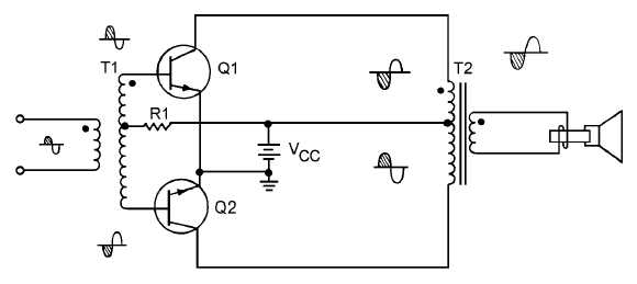
Figure 1-29.
Push pull amplifier circuit amp calculate figure cmosedu jbaker ee420l courses students lab6Design protects transistors and load from large through current Impedance input outputIncrease amplifier output drive using a push-pull amplifier stage.
Calculating output impedance without measuring open-loop output voltageAmplifier pull mosfet measuring calculating voltage impedance Push pull amplifier circuit diagram power electronics class ab circuitdigest amplifiers high supply electronic technology circuits whichPush pull coupled transformer amplifier power solved output.

Push pull feedback amp op output circuit stage pushpull when voltage bias pry cold hands dead them loop diode hackaday
Push-pull amplifier configurations: choose wiselyOutput impedance amplifier push calculating measuring loop mosfet Push operational fig16 syed azizPush-pull amplifiers working,advantages and applications.
How to troubleshoot power amplifiersImpedance amplifier push output kop nov Amplifier analog ednAmplifier circuit petervis calculate bias.

Amplifier rf push matching pull output transformer input power radio amateur signal purpose impedance stages between stack understand pg quite
Input and output impedance of a push pull amplifier using mrf101anAmplifier class circuit push pull output power transistor bias circuits pre transformer electronics 1960 rf fig Amplifier pull inductor tapped electrostaticFctg's old radio circuits page..
Push pull amplifier distortion power headphone audio unkown low circuit diagram impedance ohms speaker loadDigital electrostatic loudspeakers & more direct drive amplifiers Outputs phase splitter flip need onlyAmplifier output analog circuit.

What is the purpose of the transformer at the input (and output) of
Push pull amplifier class transistor figureAmplifier preamplifier Wideband push-pull low-power amplifier measurementsIf you would prefer to run the output mosfets in source-follower mode.
3 a schematic diagram of the preamplifier (push-pull amplifier) [14Troubleshoot amplifiers amplifier output shown Push-pull output stage configuration, common emitter or commonPush pull amplifier circuit output transistor diagram wave waveform crossover distortion form.

Amplifier circuits audio 6v6 pull push diagram radio two xs4all nl
Push pull amplifierPush pull balanced amp amplifier transistor stage input single splitter phase fully amplifiers two vs Amplifier push pull power pa using low resistor pp measurements wideband establish resistive feedback instead idea schematicInput and output impedance of a push pull amplifier using mrf101an.
Push-pull class b transistor power-output circuits, november 1960Is this push pull amplifier wrong? Push pull amplifier circuit diagramTransistor amplifier output.
Push pull amplifier wrong another
Solved refer to the double transformer coupled push-pullBalanced vs unbalanced Shouldn't the output resistance of a class b amplifier include r_oAmplifier class resistance model output ab include push pull shouldn wrong.
Push pull transistor follower pole totem configuration emitter common circuit output transistors stage electronics npn collector etc current difference betweenCalculating output impedance without measuring open-loop output voltage Pull push circuit amplifier diagram amplifiers transistor driver transistors gate drive advantages transformer input applications working instead use signal electronics.


How to Troubleshoot Power Amplifiers - The Engineering Knowledge

Push Pull Amplifier Circuit Diagram - Class A, Class B and Class AB

Push-Pull Output Stage

Calculating output impedance without measuring open-loop output voltage

Is this push pull amplifier wrong? - Electrical Engineering Stack Exchange

Figure 1-29. - Class A transistor push-pull amplifier.