Ne555 Pwm Control Schematic Diagram
Ne555 pwm dc voltage Make simple 555 inverter circuit using mosfet Ne555 based pwm dc motor speed controller circuit with pcb layout
DC Motor Speed Control Using Ne555 and IRF540 » ElectroDuino
Ne555 adjustable pwm circuit Motor control speed dc irf540 ne555 using mosfet circuit diagram pulse modulation width Pwm ne555 12v pic circuits between two circuit signals difference schematic
Pwm with ne555
Dc motor speed control using ne555 and irf540 » electroduinoNe555 schematic controller motors working power big circuitlab created using Pwm ne555 circuitNe555 okay closer.
Pwm dimmer mosfet techniquePwm generator with ne555 Ne5532 amplifier power class circuit diagramHow to generate pwm using ic 555 (2 methods explored).

Inverter mosfet ne555 power using circuit 220 volts 555 diagram ic ac dc make simple use timer circuits 50hz wave
Pwm dimmer motorLed dimmer and dc motor speed controller circuit using pwm technique Ne555 pwm circuit controller3 (bass mid treble) tone control circuits projects using ne5532.
Circuitlab ne555 pwmNe5532 tone control circuit ic stereo pre using lm324 bass diagram schematic treble mid circuits preamp amp op wiring controls Ne555 pwm controller circuitPwm ne555 timer ic circuit but adjusted oldschool p1 dynamic static.

Pwm 555 circuits generating generate explored simplest below
Led dimmer and dc motor speed controller circuit using pwm technique .
.


3 (bass mid treble) Tone control circuits projects using NE5532

PWM with NE555

PWM generator with NE555 - CircuitLab

NE555 based PWM DC Motor Speed Controller Circuit with PCB Layout

How to Generate PWM Using IC 555 (2 Methods Explored) - Homemade

microcontroller - Difference between two 12V PWM signals/circuits (PIC

DC Motor Speed Control Using Ne555 and IRF540 » ElectroDuino
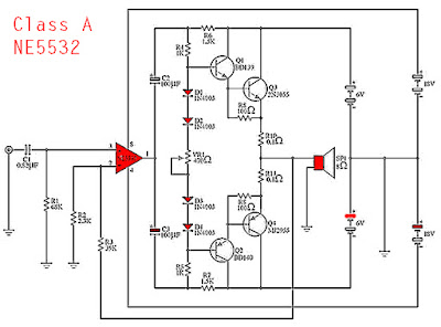
NE5532 - Class A Power Amplifier - Electronic Circuit

LED Dimmer and DC Motor Speed Controller Circuit Using PWM Technique